Table of Contents
CAN Physical Layer
CAN can be used with different physical layer characteristics. Some of them are described in the ISO11898 standards some not.
Often asked questions regarding the physical layer are regarding commonly used bit rates and CAN cable length.
High Speed CAN -- ISO 11898-2
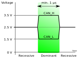
The picture shows the two signal states recessive and dominant and its signal levels for the CAN high speed version with 1 Mbit/s. Since Dec 2016 ISO11898-2:2016 is published specifying bit rates above 1 Mbit/s
Differential signaling on twisted cable lines
Differential signaling - best practices by Clark Kinnaird.
CAN Termination
Read more about CAN line termination, why often it is 120 Ω, and something about the theory on the section about CAN line termination.
The NXP application note AN10211 (TJA1040 high speed CAN transceiver) explains in detail the Split termination concept
High Speed with selective wake-up functionality
Karsten Penno explaining NXP CAN Partial Networking in a Youtube Video
The article “Energy saving in automotive electronics architectures”, Thomas Liebetrau, Ursula Kelling, Tobias Otterer, Magnus Hell, all of them with Infineon Technologies AG, describes basics and application fields. Published “CAN Newsletter 4/2012, CiA.
Road vehicles -- ISO 11992-1
ISO 11992-1 Road vehicles – Interchange of digital information on electrical connections between towing and towed vehicles – Part 1: Physical and data-link layers
The ISO 11992-1 compliant CAN transceiver produced by Atmel is discontinued (2013). Wabco has developed jointly with ON Semiconductors an equivalent transceiver. Interested parties may contact CiA.
CAN Transceivers
CAN Transceivers are interfaces to the CAN controller and to the CAN bus. Its task is to adapt the logic level signals from the CAN controller to the signal levels on the CAN bus.
Different physical layers are described in various ISO 11898 Documents, see below
- ISO11898-2 HighSpeed CAN
- ISO11898-3 LowSpeedFaultTolerant CAN
A common transceiver for the physical layer defined by ISO 11898-2 (high-speed) is NXP TJA1044GT.
CAN transceivers are tested by the C&S group (Germany) using the GIFT/ICT CAN High-Speed Transceiver Conformance Test. The page Conformance Testing explains the test strategies in detail. Furthermore, the site includes a link to the newest version of the “Interoperability test specification for high-speed CAN transceiver or equivalent devices”.
Other transceivers are TJA1054 for ISO 11898-3 (low-speed fault-tolerant CAN FaultTolerantCAN) and AU5790 (for SAE J2411 single-wire CAN).
More information about different physical layers is available at CiA.
The question: “Are there any compatibility problems with using a mixed 3.3V and 5V transceiver network?” was answered by Steve Corrigan s-corrigan1@ti.com: “I have a bus with 30 3.3-V HVD230s and 30 5-V 82C250s and have no problems.”
Nowadays all micro controllers don't work anymore with 5V but 3.3V. To get ideas for the CAN bus transceiver designs in 3.3 V system read Top five reasons to use 3.3V CAN transceivers.
Some of the transceivers, e.g. NXP TJA1041, try to detect own problems by a feature called DOMINANT CLAMPING DETECTION. With this feature they introduce a low bit rate limit: TJA1041 Chapter TXD DOMINANT CLAMPING DETECTION: ….. The tdom(TXD) timer defines the minimum possible bit rate of 40 kbit/s. Other namings are Dominant Timeout.
The dominant time-out circuit prevents the driver from blocking network communications if a local CAN controller fault occurs. The time-out circuit is triggered by a falling edge on TXD. If no rising edge occurs on TXD before the time-out of the circuits expires, the driver is disabled to prevent the local node from continuously transmitting a dominant bit. If a rising edge occurs on TXD, commanding a recessive bit, the timer will be reset and the driver will be re-enabled. The time-out value is set so that normal CAN communication will not cause the dominant time-out circuit to expire.
Often it is required that the device electronic is galvanically decoupled from the CAN bus. In this case in the past opto couplers were used. These opto couplers are expensive and they add a noteworthy amount of propagation delay into the signal path. TI is offering dual-channel digital isolators with a very small amount of propagation delay of 16ns. ISO7221M active Dual Channel, 1/1, 150Mbps Digital Isolator.
CAN transceivers integrated with the CAN controller
NXP announced the first micro controller with integrated CAN controller and physical layer transceiver in January 2011. The System-in-Package-solutions LPC11C22 and LPC11C24 with integrated Transceiver TJF1051 are offered in LQFP48 housings.
Holt Inc. offers a stand alone CAN controller with transceiver HI-3110.
System Basis Chip (SBC)
In addition to the typical supply and communication functions (voltage regulator, watchdog, SPI, CAN and LIN transceiver), they often
incorporate other, application-specific functions, such as high- and low-side drivers.
Typical use in cars particularly in control units of the body electronics.
CAN Repeaters
details related to CAN repeaters
CAN Switches
details related to CAN Switches
Wireless CAN
CAN over Fibre Optic
CAN network protection
CAN networks are used in different environments. Electro Static Discharge (ESD) robustness is a key issue in some if not all of them. NXP offers network protection diodes. The PESD1CAN (PDF) CAN network protection diode and the successor PESD1CAN-U (PDF data sheet) PESD1CAN-U CAN network protection diode. It comes in an SOT323 (SC-70) package and is able to protect two CAN network lines.
